


When you blend a smoothie or soup, the blender blade design and how they move through liquid determines how smooth or uneven your results will be. The way the blades create a vortex inside the jar affects how ingredients circulate and break down.
Poor design or speed control can cause cavitation—tiny air pockets that interrupt blending, create noise, and reduce efficiency. To avoid cavitation, you need blades that maintain a steady vortex and balance pressure across the jar.
You can control cavitation by understanding how blade geometry, speed, and jar shape interact. The right angle, edge type, and spacing between blades help maintain strong, even flow without forming low-pressure zones. This keeps the mixture moving smoothly and prevents the bubbles that cause vibration and wear. Designing or choosing a blender with these features ensures consistent performance and longer-lasting parts.
Key Takeaways
- Cavitation happens when poor blade or vortex design disrupts smooth blending.
- Balanced blade geometry and controlled vortex flow prevent air pockets and noise.
- Proper design choices improve performance, durability, and blending consistency.
Top recommended blenders in 2026
-
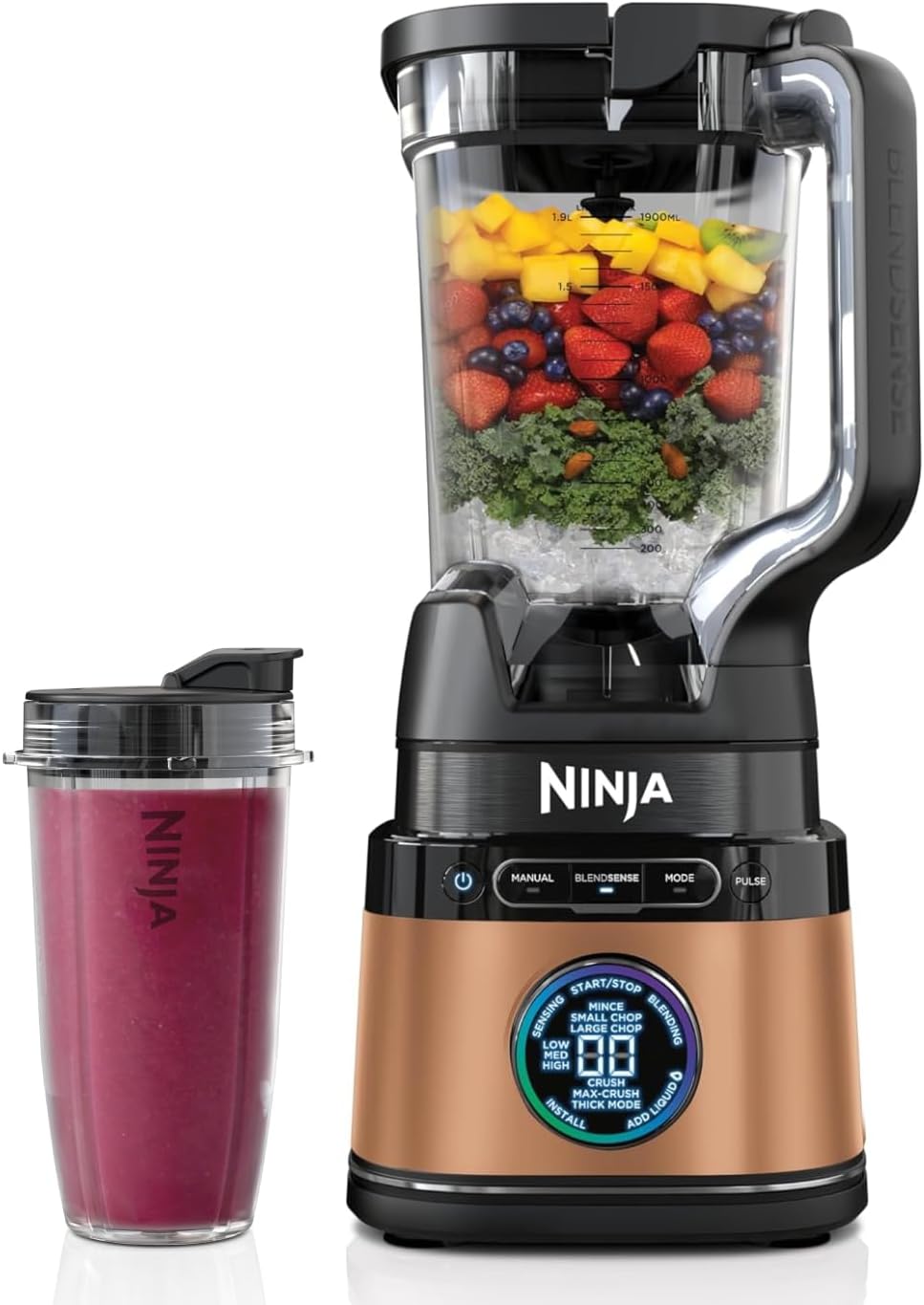
- AMAZON EXCLUSIVE: Black and Copper Ninja Detect Power Blender Pro & Single Serve. BlendSense Technology intelligently detects ingredients, portion size and ice, then auto adjusts speed, time and pulse for perfectly smooth results.
- 2 BLENDERS IN 1: Save space with this traditional jug blender & personal blender in one. Create dips, sauces & smoothies in the single-serve cups. Or blend frozen cocktails & smoothies in the large jug.
- DETECT DIAL: Easy-to-read dial lets you take full control of blending, chopping & more. Select from 15+ functions (14 manual and 4 automatic modes). Also includes countdown timer & ‘Add liquid’ notification.
- AUTO, MANUAL & PRESET MODES: Ninja Detect Blenders let you take as little or as much control as you like in the kitchen. Enjoy automatic BlendSense Technology, 10 speeds & handy preset modes.
- INCLUDES: 1200W Motor Base (UK Plug), 2L Jug with Lid (1900 ml max liquid capacity), 2x 680ml Single Serve Cups (644 ml max liquid capacity), Ninja Detect Total Crushing & Chopping Blade, Hybrid Edge Blades, Inspiration & Recipe Guide.
- DIMENSIONS: H: 44.5 x W: 21 x D: 17.5 cm. Weight: 4.83 kg. Colour: Black. 2-year guarantee upon registration with Ninja (UK & ROI only).
- THE UK’s NO.1 BLENDER BRAND*: UK market data, sales by value Jan 24 – Dec 24
-

- Optimum blending: a 600W motor, four robust stainless-steel blades and a tapered jug shape combine for efficient blending without chunks, every time. It even crushes ice with ease.
- Cool running: the built-in air cooling system optimizes airflow through the motor to keep things cool, prevent overheating and extend the life of your blender.
- Solid performance: Four suction feet keep Blendforce II stable on your worktop, no matter how tough the ingredients.
- Easy to use: with a two-speed (plus pulse) rotary dial for custom blending, 1.25L capacity for big batches, ergonomic handle for comfort, and dishwasher-safe, removable parts for easy cleaning.
- Safe: the secure lock system shows you when the jug is locked securely onto the base, while the smart lid with filling hole lets you add ingredients safely and easily when the blender is in use.
-
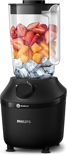
- Smooth blends, no lumps: Powerful 450 W motor for smooth results in just 45 seconds* – With 1 speed, Pulse function and up to 19000 rotations per minute for fast, consistent blends
- Family sized: Blender smoothie maker for the whole family – Large 1.9-litre jug prepares up to 5 servings at a time (based on 200 ml glass size)
- Unique technology: Our ProBlend system combines motor, blade shape and jug design for optimal blending flow and cutting power to take on all ingredients and even crush ice
- Personalised recipes: Make healthy homemade smoothies, soups and more with our HomeID App – Find inspiring recipes personalised to your preferences and follow them easily step-by-step
- What’s in the box: Food Blender, dishwasher-safe plastic jug
-

- POWERFUL PERFORMANCE: 600-watt motor with stainless steel Sabre ice blades for crushing ice and blending frozen ingredients
- VARIABLE SPEED CONTROL: Easy to operate with 2 simple speed settings and Pulse function for precise blending control
- FAMILY-SIZED CAPACITY: Generous 1.5-liter BPA-free container perfect for family portions and meal prep – safe and healthy for your loved ones
- EFFORTLESS CLEANUP: All removable parts are dishwasher safe, including jug, blades, and lid – making cleanup quick and hassle-free
- PRODUCT DIMENSIONS: Measures 16.9 x 21.2 x 37.9 cm (WxDxH)
-
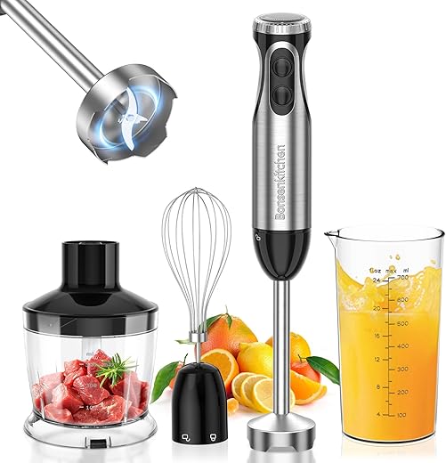
- Sufficient power: Bonsenkitchen hand blender is equipped with a high performance 1000W motor and 4 blades, made of stainless steel materials, which is durable and ideal for efficiently chopping hard ingredients such as nuts and meat, reducing food preparation time.
- 20-Speed Adjustable + Turbo Button: Professional 20-speed variable speed hand blenders, you can easily adjust the speed and power according to different foods. The TURBO button instantly reaches maximum power for better results.
- Easy to use and clean: Ergonomic handle provides a non-slip, comfortable grip for easy control of the stirring stick. Safe and secure button lock. Handheld blender with removable accessories can be cleaned after rinsing (main unit cannot be immersed in water)
- 4-in-1 hand blender set: Includes stainless steel immersion blender, whisk, 500ml chopping bowl, 700ml measuring cup. Many options are available to you: soups, sauces, mayonnaise, purees, baby food and more.
- Safety and quality assurance: All food contact parts of the hand blender for kitchen are BPA free. We stand behind the quality of our product and offer technical support. if you have any questions, please contact us first, we will provide you with a satisfactory solution as soon as possible.


Fundamentals of Cavitation and Vortex Formation
Understanding how cavitation and vortex flow interact helps you improve blending performance and protect your equipment. These fluid dynamics principles explain why blade design, jar shape, and blending speed affect texture, consistency, and noise levels.
What Is Cavitation?
Cavitation happens when pressure in a liquid drops below its vapour pressure, forming small vapour bubbles. These bubbles collapse when they move into higher-pressure zones, releasing energy that can cause noise, vibration, and surface wear.
In blenders, cavitation often occurs near the blade tips where pressure changes rapidly. The collapsing bubbles can erode metal surfaces and reduce blending efficiency.
You can think of cavitation as a localised boiling effect caused by low pressure, not by heat. It’s a natural part of fluid flow at high speeds but becomes a problem when uncontrolled. Managing blade speed and liquid levels helps reduce this effect and maintain smooth operation.
Types of Cavitation in Blenders
Cavitation can appear in several forms depending on the flow conditions. The most common types relevant to blenders include:
| Type | Description | Common Location |
|---|---|---|
| Sheet Cavitation | Forms as a thin layer of vapour attached to a surface. | Along the blade face. |
| Bubble Cavitation | Appears as isolated vapour bubbles that form and collapse quickly. | Around blade edges. |
| Vortex Cavitation | Develops in the low-pressure core of a rotating vortex. | Near the blade tips. |
| Tip Vortex Cavitation | A specific form of vortex cavitation that originates at the blade tip. | Trailing edge of the blade. |
Each type affects performance differently. Sheet and tip vortex cavitation are the most likely to cause wear and vibration in high-speed blenders. Recognising these patterns helps you adjust speed, load, or liquid volume to reduce damage.
Role of Vortex in Fluid Flow
The vortex forms when rotating blades draw liquid downward, creating a spiral flow toward the centre. This motion, known as vortex flow, mixes ingredients efficiently by pulling solids into the blades.
A well-shaped vortex improves circulation and reduces dead zones in the jar. However, if the vortex becomes too strong, pressure at the core drops sharply, increasing the risk of cavitation.
Blade angle, jar geometry, and liquid viscosity all influence vortex strength. Smooth jar walls and balanced blade design help maintain a stable vortex. You should aim for a vortex that promotes even mixing without forming a deep funnel that exposes the blades.
Cavitation Inception and Shedding
Cavitation inception marks the point where vapour bubbles first appear. It depends on local pressure, blade speed, and fluid properties. The lower the pressure at the vortex centre, the earlier cavitation begins.
Once formed, bubbles may detach and move with the flow, a process called cavitation shedding. This cycle of formation and collapse produces noise and vibration, which can harm the blender’s surfaces over time.
You can limit inception by keeping enough liquid above the blades and avoiding excessive speeds. Proper layering of ingredients also helps stabilise the flow and maintain consistent pressure around the blades. Monitoring these factors keeps cavitation within safe limits and extends your blender’s lifespan.
Blade Geometry and Its Impact on Cavitation
The geometry of a blade directly affects how fluid moves around it and how pressure changes along its surface. Small variations in shape, clearance, or pitch can determine whether cavitation forms and how severe it becomes in systems such as propellers, axial flow compressors, and waterjet pumps.
Blade Shape and Tip Design
Your blade’s shape controls how pressure and velocity distribute across the surface. A well‑balanced camber and thickness reduce local pressure drops that often trigger cavitation. Sharp leading edges or abrupt curvature changes can cause low‑pressure zones where vapour bubbles form.


Tip design plays a major role. Rounded or swept‑back tips help stabilise the flow and weaken the tip vortex that often leads to cavitation inception. In contrast, blunt or squared tips increase turbulence and pressure fluctuations.
Researchers studying propeller and hydrofoil blades have found that smoother tip transitions delay cavitation by improving flow attachment. You can also use serrated or winglet‑type tips to redirect the vortex path and reduce energy loss.
| Tip Feature | Cavitation Effect | Typical Use |
|---|---|---|
| Rounded tip | Delays inception | Propellers, pumps |
| Swept‑back tip | Reduces vortex strength | Hydrofoils |
| Serrated edge | Disrupts vortex core | Experimental blades |
Tip Clearance and Tip Leakage Flow
Tip clearance—the small gap between the blade tip and the casing or duct—strongly affects tip‑leakage vortex formation. When the clearance is too large, high‑pressure fluid from the pressure side leaks to the suction side, forming a swirling vortex that lowers local pressure and promotes cavitation.
You should keep the clearance as tight as manufacturing limits and thermal expansion allow. In axial compressors and waterjet pumps, reducing clearance improves efficiency and delays cavitation inception. However, extremely small gaps may increase friction or cause rubbing, so a balanced design is essential.
Visual studies of partial propeller blades show that leakage vortices collapse violently when interacting with re‑entrant flow. This collapse produces noise and vibration, so controlling leakage flow is key to smoother operation and longer blade life.
Effect of Blade Number and Pitch
The number of blades and their pitch angle influence both thrust and cavitation behaviour. Increasing the blade number distributes the load more evenly, lowering the pressure difference on each blade and reducing tip vortex strength. However, more blades can slightly reduce efficiency due to added surface drag.
Pitch angle determines how much the blade accelerates the fluid. A higher pitch increases thrust but also raises the risk of low‑pressure zones on the suction side. You should match pitch to the operating speed and fluid density to maintain stable flow without reaching vapour pressure.
Numerical studies of propeller blades show that optimised pitch and blade count can cut cavitation by up to one‑third compared with conventional designs. These adjustments also reduce vibration and noise levels in both marine and compressor applications.
Hydrofoil and Propeller Blade Influences
Hydrofoil and propeller blade research provides useful insight into cavitation control. Both rely on maintaining smooth pressure gradients along the chord and avoiding abrupt curvature near the trailing edge. You can apply similar design rules to blender or pump blades that operate in liquid environments.
Hydrofoils with moderate camber and thickness ratios show delayed cavitation inception because they maintain higher minimum pressures. Propeller blades benefit from comparable profiles, especially near the tip region where the tip vortex forms.
In axial flow compressors or cascades, the same principles apply. Adjusting the camber line and leading‑edge radius helps stabilise the boundary layer, preventing local pressure drops. By aligning your blade design with proven hydrofoil data, you can achieve better efficiency and minimise cavitation across a range of flow conditions.
Vortex Control Strategies to Prevent Cavitation
You can reduce cavitation by controlling how vortices form and behave around the blade tip. Effective design methods focus on reshaping the flow field, lowering pressure gradients, and improving energy transfer efficiency through both structural and computational strategies.


Grooves and Winglets for Vortex Suppression
Adding grooves or winglets near the tip helps manage the tip vortex flow field. Grooves create small secondary flows that weaken the main vortex, reducing the low-pressure zone where cavitation begins. Winglets redirect the flow path, limiting the strength of the rotating wake behind the blade.
In laboratory and numerical studies, overhanging grooves (OHGs) and micro vortex generators have shown that they can delay vortex cavitation inception. These features promote vorticity dispersion and stabilise the pressure field near the tip.
Designers often adjust groove depth or winglet angle to balance flow stability and efficiency. Too-deep grooves may increase drag, while shallow ones may not affect the vortex enough. Testing these parameters under different load conditions helps you find the best combination for your specific blade geometry.
Ducted Propeller and Casing Aspiration
A ducted propeller surrounds the blade tips with a short annular shroud. This design reduces tip leakage and limits pressure differences between the suction and pressure sides. The duct also straightens the wake, lowering the risk of cavitation in the vortex core.
Casing aspiration takes this further by drawing air or water through small openings in the duct wall. The flow injection modifies local pressure and weakens vortex rotation. You can use this technique to control vorticity and suppress cavitation without major changes to the blade shape.
However, the system must be tuned carefully. Poorly positioned aspiration ports can cause uneven flow and reduce propulsion efficiency. When designed properly, the duct and aspiration combination offers a reliable passive control method for both marine and mixing applications.
Numerical and Large Eddy Simulation Approaches
Numerical simulation and large eddy simulation (LES) help you analyse vortex behaviour before physical testing. LES resolves large-scale turbulent structures, giving detailed insight into vorticity and pressure fluctuations near the blade tip.
By using stereo-PIV data and validated computational models, you can visualise how design changes affect the tip vortex flow field. These tools identify unstable zones and predict cavitation onset more accurately than traditional steady-flow models.
Modern solvers such as OpenFOAM allow you to test different groove depths, duct geometries, and aspiration rates. This approach reduces prototype costs and improves design reliability by showing how each modification influences flow stability and cavitation risk.
Performance Optimisation and Noise Reduction
Improving energy performance, reducing hydrodynamic losses, and managing underwater radiated noise depend on how efficiently you control blade geometry, surface finish, and flow behaviour. Careful balance between performance and quiet operation ensures smoother blending and longer equipment life.

Energy Performance and Efficiency
You can enhance energy performance by refining the blade profile and tip clearance to minimise flow separation and drag. A smoother flow path reduces the energy wasted in turbulence and improves mixing efficiency.
Use computational fluid dynamics (CFD) analysis to assess how design changes affect pressure distribution and flow uniformity. Lower pressure differences across the blade reduce cavitation risk and energy loss.
| Design Factor | Effect on Efficiency |
|---|---|
| Tip clearance | Smaller gaps reduce leakage flow |
| Blade angle | Optimised pitch improves thrust |
| Surface finish | Smooth surfaces lower friction |
Regular maintenance, including sharpening and balancing, keeps the motor load stable and prevents unnecessary power draw.
Integrated Performance Index (IPI)
The Integrated Performance Index (IPI) combines several performance indicators—such as flow rate, power consumption, and noise level—into one measurable value. Tracking this index helps you evaluate how design or operational changes affect overall performance.
You can calculate IPI from both experimental and simulated data. It reflects how efficiently your system converts electrical power into useful mixing or pumping work without excessive vibration or cavitation.
A higher IPI indicates better energy use and lower mechanical stress. When you adjust blade geometry or motor speed, monitor how the IPI changes under different load conditions. This helps identify the most stable and efficient operating range.
Underwater Radiated Noise and Turbulence
Underwater radiated noise (URN) results from pressure fluctuations and vortex shedding around the blades. Reducing URN involves managing turbulence intensity and preventing cavitation bubbles from collapsing near the blade surface.
You can lower noise by refining the trailing edge shape, using anti-vortex tips, and maintaining smooth inflow conditions. Even small improvements in flow uniformity reduce tonal noise and vibration.
Applying damping materials around the housing and ensuring proper alignment between motor and shaft also help control structural noise transfer through the system.
Frequently Asked Questions
Efficient blending depends on how blade geometry, motor speed, and material properties interact with the liquid being processed. Understanding these factors helps you prevent cavitation, maintain smooth vortex flow, and extend the lifespan of your blender blades.
What factors influence the formation of cavitation in blender blade systems?
Cavitation occurs when pressure drops around fast-moving blades, forming vapour bubbles that collapse and cause surface damage. You’re more likely to see this when operating at high speeds with low-viscosity liquids. Blade angle, jar shape, and motor power also influence how evenly pressure distributes during blending.
How can blade shape and angle be optimised to minimise cavitation in high-speed blenders?
You can reduce cavitation by using blades with moderate angles that maintain consistent flow. Slightly tilted or curved edges help control pressure zones and guide liquid smoothly through the vortex. Multi-tier or cross-pattern designs also improve circulation, preventing air pockets from forming near the blade tips.
What materials are best suited for crafting blades that resist cavitation?
Stainless steel remains the most reliable material because it resists corrosion and withstands repeated bubble collapse. Titanium-coated or hardened steel blades offer extra durability and maintain surface smoothness longer. These materials also handle high temperatures and stress without warping or pitting.
Can the speed and power settings of a blender affect the likelihood of cavitation occurring?
Yes. Running your blender at maximum speed with thin liquids can create excessive pressure differences that trigger cavitation. Gradually increasing speed or using pulse functions helps stabilise flow. Matching power output to the viscosity of your ingredients keeps the vortex stable and reduces bubble formation.
What are the signs of cavitation damage in blender blades and how can it be prevented?
You may notice small pits, dull edges, or rough patches on the blade surface. These are signs of repeated bubble collapse. To prevent damage, avoid over-speeding, maintain clean blades, and ensure proper blade-to-jar clearance. Using thicker mixtures or adjusting angles can also help reduce cavitation stress.
How does the viscosity of blended materials impact cavitation and vortex formation?
Thicker mixtures cushion pressure changes, making cavitation less likely. Thin or watery liquids, however, allow bubbles to form more easily in low-pressure zones. Adjusting speed and blade angle to match the viscosity ensures a steady vortex and consistent blending performance.
Informative video


